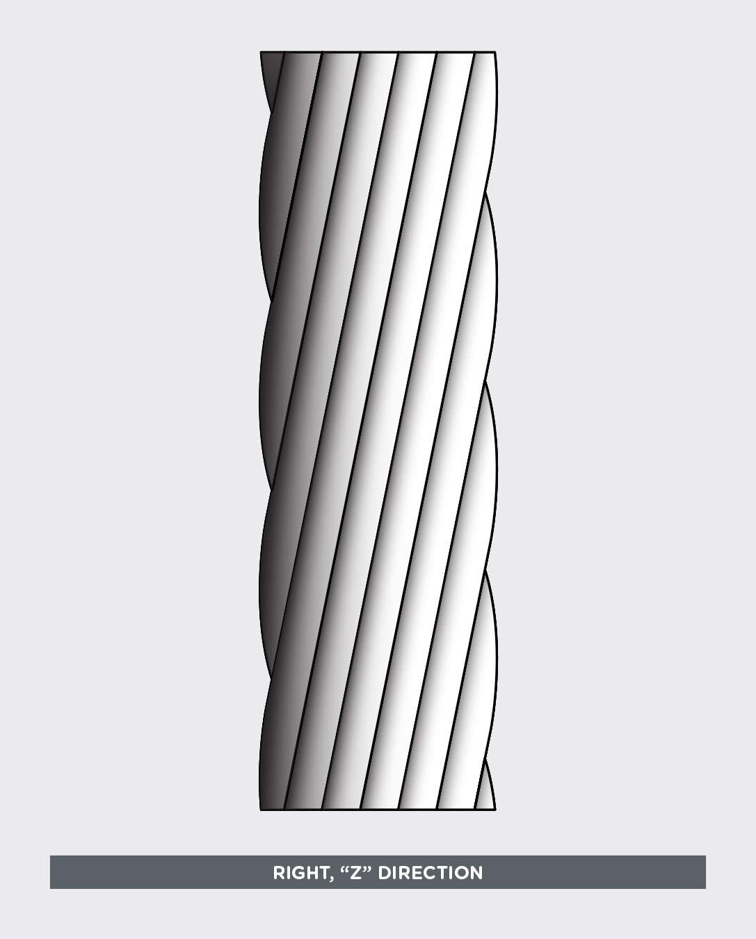
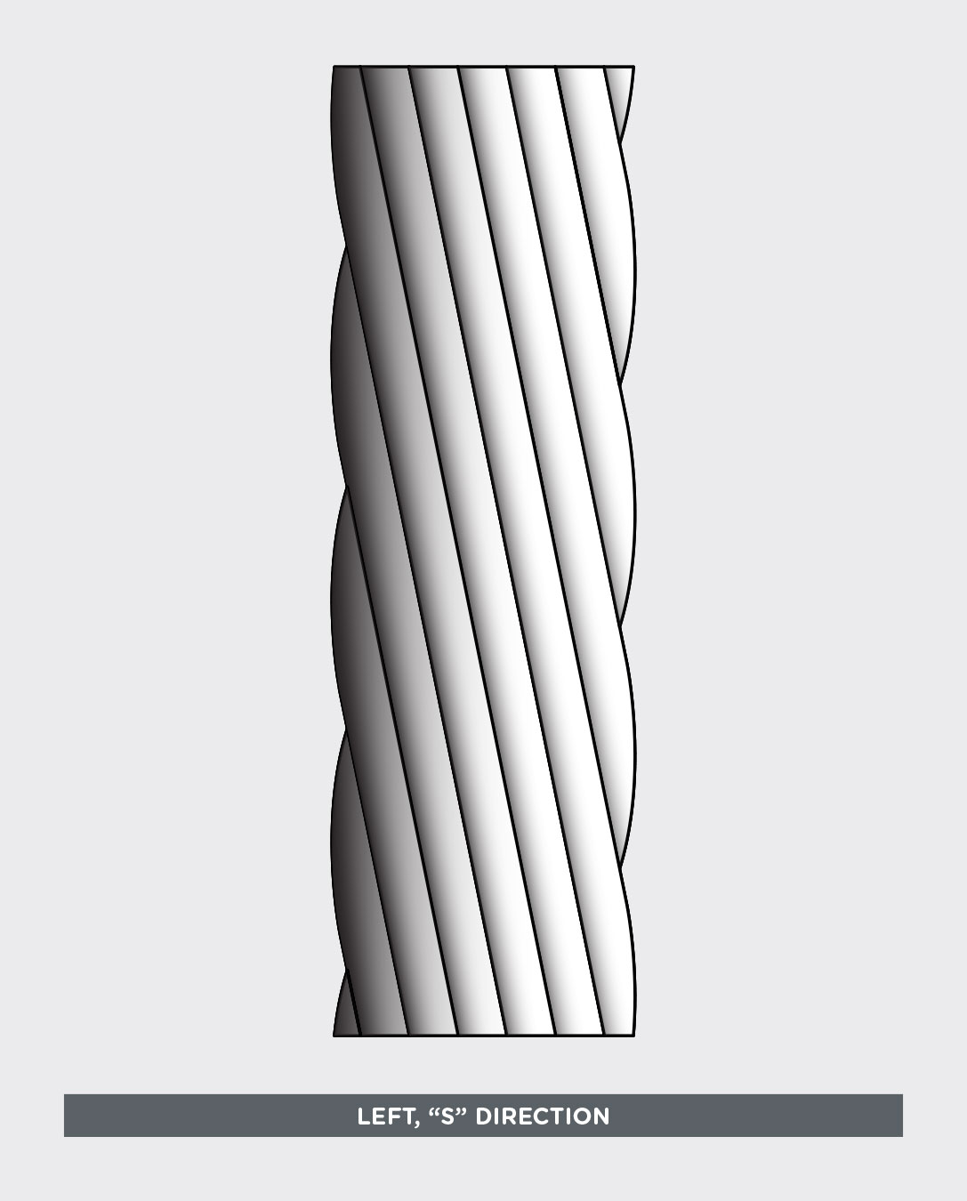
Stranded conductors are manufactured by twisting strands of non-insulated wire. The direction of twisting is designated as the “lay direction.” The degree of twist per unit length defines the “lay length.”
Lay Direction
The lay direction is determined by the direction the machine is turning during the stranding operation. The conventional method to determine the lay direction is to observe the upper surface of the stranded conductor with one end pointing toward you and the wire leading away from you.


If the strands turn left leading away from the observer and have the same slant as the middle of the letter “S”, the convention denotes an “S” lay direction.
If the strands turn right leading away from the observer and have the same slant as the middle of the letter “Z”, the convention denotes a “Z” lay direction.
Lay Length
Lay length is defined as the distance required to complete one revolution of the strand around the diameter of the conductor.

When a conductor has more than one layer, it usually refers to the lay length of the outer layer. In the case of Unilay, Equilay and bunch, the lay length of all layers is equal. In True Concentric and Unidirectional, the lay lengths of the inner layers are less, this also holds true for rope constructions.
Generally Accepted Practices
There are some general practices that pertain to the lay direction and lengths of conductor as specified by industry standards such as ASTM, NEMA and military, however, requirements for specific applications vary.
Direction of the Outer Layer:
The direction away from the outer layer of strands or members is usually S. Inner layer directions depend upon the construction (True concentric, Unilay, etc).
Length of the Outer Layer:
The lay length of the outer layer of strands or members varies with different applications.
- For most conductor applications, lay lengths of between 8 – 16 times the outer diameter of a given layer are specified in ASTM B 286. In general, lay lengths in the range of 12 – 15 times the outer diameter are used for tighter tolerance and geometric pattern control. Shorter lay lengths of 12 times or less have the disadvantage of slightly higher weight per unit length.
For 7 strand and bunch applications, where tight diameter tolerance is less of a concern, lay lengths in excess of 30 times the outer diameter are common. Longer lay lengths are sometimes preferred by customers for cost, yield and weight considerations.
Stranding Factors
The increase in weight and resistance due to stranding can be calculated mathematically. ASTM refers to this increase as the stranding or “k-factor”, defined as “incremental percentage (increase) of weight and electrical resistance.” ASTM B 8, B 229, B 231, and others give a method of calculating the “k“:
k = 100 (m – 1)
Where k is the incremental (increase) in mass and electrical resistance, the factor m is the ratio of the mass or electrical resistance of a unit length of the stranded conductor to that of a conductor monofilament of the same section or that of the stranded conductor with an infinite length of lay (all the strands run parallel to the axis). The factor m of the strand is the average of the factors for each of the individual wires in the conductor including the straight wire core, if any (for which the lay factor is unity).
The lay factor mind for any given wire in a concentric stranded conductor is calculated as follows:
![]()
Where n = (length of lay) + (diameter of helical path of wire).
Example: the lay factor for a 19 strand conductor is the numerical average of the 19 individual strands:
m = (1 + 6m6 = 12m12) ÷ 19
Where m6 = mind calculated for each of the 6 strands of the inner layer and m12 = mind calculated for each of the 12 strands of the outer layer.
